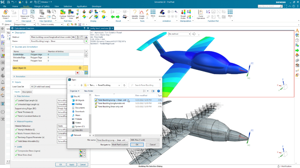
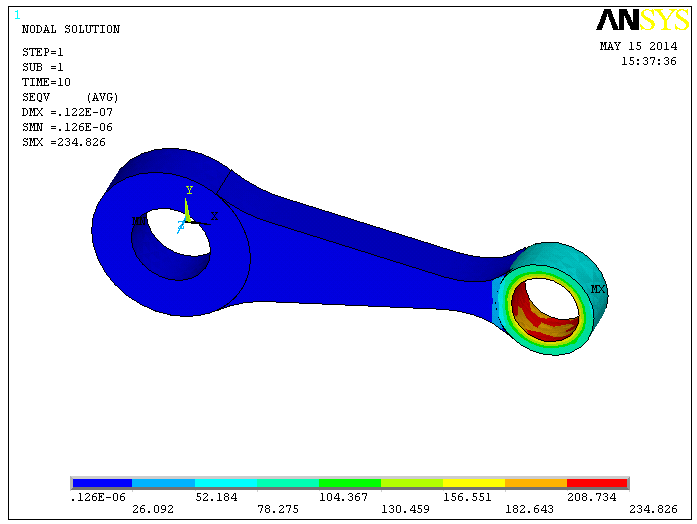
Computerised stress analysis is the use of numerical models—most commonly the finite element method (FEM)—to predict how a part, structure, or tissue carries loads, deforms, and fails. In plain terms: you build a digital replica, tell it what materials and forces to expect, and the computer estimates stresses, strains, and safety margins before you cut metal or go to clinic.
What it involves
Geometry: a CAD model of the component or anatomy.
Materials: elastic/plastic properties (E, ν, yield strength), or viscoelastic/anisotropic data for composites and biological tissue.
Loads & restraints: forces, pressures, accelerations, temperature, contact, and boundary conditions.
Meshing: dividing the geometry into small elements so the solver can approximate the governing equations of continuum mechanics.
Solving & post-processing: compute fields (σ, ε, displacement), factors of safety, hot spots, and visualize contours, vectors, or animations.
Typical analyses
Linear static: small deflections, proportional stress–strain (quick “first pass”).
Nonlinear: large deformation, plasticity, contact, hyperelasticity (rubbers, vessels).
Dynamic: vibration (modal), transient shock, random response.
Thermal & coupled: heat transfer, thermo-mechanical stress.
Stability & life: buckling, fatigue/damage, fracture (SIF/CTOD).
Core methods and tools
FEM (standard): general-purpose structural analysis.
BEM / FDM / meshless: niche cases, acoustics, fracture fronts, etc.
Common platforms: Ansys, Abaqus, Nastran, COMSOL, SolidWorks Simulation—plus open-source (Code_Aster, CalculiX).
Why it’s valuable
Design faster, safer: explore “what-ifs” early, reduce prototypes, meet codes.
Insight: see loads you can’t easily measure; guide material choices and geometry.
Compliance & documentation: traceable inputs/outputs for engineering and regulatory files.