What is a Warren truss?

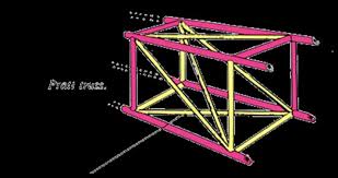
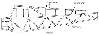
The term “Warren Truss” refers to a type of structural design, and it has been used in many aircraft, primarily as interplane struts on biplanes and for the fuselage or wings. Not to be confused with the Australian Politician Warren Errol Truss, who served as the 16th deputy prime minister of Australia and the minister for Infrastructure and Regional Development in the Abbott government and the Turnbull government.

Examples include the interplane struts on the Handley Page H.P.42 and Fiat CR.42, and for the fuselage frame of planes like the Piper J-3 Cub and Hawker Hurricane. The design is also featured in modern model aircraft construction; as follows:

-Handley Page H.P.42: An early British airliner that featured Warren truss interplane struts.


-Fiat CR.42: An Italian fighter aircraft from the World War II era that also used Warren truss bracing.


-Ansaldo SVA: A series of fast Italian reconnaissance biplanes from World War I that were built with this design.


-Piper J-3 Cub: A well-known civilian aircraft that uses a Warren truss design for its fuselage frame.


-Hawker Hurricane: A famous British fighter from WWII, which also incorporated this truss design in its fuselage construction.

Key aspects of the FEA process


Model creation: A CAD model of the fuselage truss is imported into FEA software like Ansys Workbench.
Material definition: The appropriate material properties are assigned to the truss elements (e.g., aluminum alloy, composite materials like CFRP).


Load and boundary conditions:
Loads: Simulate flight loads, such as pressure on the fuselage, and loads from other components like wings, engine, and landing gear.


Boundary conditions: Apply constraints to represent how the structure is supported, such as fixing certain edges.


Meshing: The geometry is discretized into a mesh of smaller elements (e.g., beam or shell elements) for the analysis to solve.


Solution: The FEA solver calculates the stresses, strains, and deformations throughout the structure based on the applied loads and boundary conditions.


Post-processing: Results are visualized as plots and animations to show how the truss deforms and where the highest stresses occur.

Finite Element Analysis (FEA) of an aircraft fuselage

Finite Element Analysis (FEA) of an aircraft fuselage truss is a method used to simulate and analyze the structural performance of a truss-like fuselage, which is a rigid framework of members like beams and struts.

FEA models the truss as a system of interconnected elements to calculate deformations, stresses, and strains under various load conditions, ensuring the structure meets performance requirements like strength and minimum weight.

This process is crucial for modern aircraft design optimization, helping to create lightweight yet strong structures

Computerised Stress Analysis for lawyers

Computerised stress analysis is the use of numerical models—most commonly the finite element method (FEM)—to predict how a part, structure, or tissue carries loads, deforms, and fails. In plain terms: you build a digital replica, tell it what materials and forces to expect, and the computer estimates stresses, strains, and safety margins before you cut metal or go to clinic.

What it involves

Geometry: a CAD model of the component or anatomy.

Materials: elastic/plastic properties (E, ν, yield strength), or viscoelastic/anisotropic data for composites and biological tissue.

Loads & restraints: forces, pressures, accelerations, temperature, contact, and boundary conditions.

Meshing: dividing the geometry into small elements so the solver can approximate the governing equations of continuum mechanics.

Solving & post-processing: compute fields (σ, ε, displacement), factors of safety, hot spots, and visualize contours, vectors, or animations.

Typical analyses

Linear static: small deflections, proportional stress–strain (quick “first pass”).

Nonlinear: large deformation, plasticity, contact, hyperelasticity (rubbers, vessels).

Dynamic: vibration (modal), transient shock, random response.

Thermal & coupled: heat transfer, thermo-mechanical stress.

Stability & life: buckling, fatigue/damage, fracture (SIF/CTOD).

Core methods and tools

FEM (standard): general-purpose structural analysis.

BEM / FDM / meshless: niche cases, acoustics, fracture fronts, etc.

Common platforms: Ansys, Abaqus, Nastran, COMSOL, SolidWorks Simulation—plus open-source (Code_Aster, CalculiX).

Why it’s valuable

Design faster, safer: explore “what-ifs” early, reduce prototypes, meet codes.

Insight: see loads you can’t easily measure; guide material choices and geometry.

Compliance & documentation: traceable inputs/outputs for engineering and regulatory files.

Product liability

Source: www.fasterway.com.au

This is a typical fracture surface. This is a threaded connection (hence the appearance of a depression around the circumference).

The fracture surface was smooth, flat, and perpendicular to the principal axis of the bolt. Crack progression marks (beach marks) extended radially from one side of the bolt and covered approximately 90% of the fracture surface area. The remaining small region towards the outer edge of the bolt exhibited features consistent with an overstress failure. The large area of fatigue cracking and small overstress area indicated that failure of the bolt was due to high cycle low stress fatigue cracking.

Bolt fracture surface showing evidence of fatigue crack progression (beach) marks

Bolt fracture surface showing evidence of fatigue crack progression (beach) marks

Source: ATSB

On 30 May 2015, a Fasterway powered parachute, recreational registration 19-7677, collided with terrain near Theodore, Queensland. The pilot, the sole occupant, died as a result of the accident.

Submitted eyenut and fractured bolt

Source: ATSB – Investigation title: Technical assistance to Recreational Aviation Australia in the examination of a fractured eyebolt from the collision with terrain involving a Fasterway Powered Parachute, near Theodore, Qld. on 30 May 2015

Investigation number: AE-2015-075

Liability for aircraft components

This presentation was delivered by Dr WIlliam Higgs and Geoffrey Parker SC of Elizabeth Street Chambers to the NSW Branch Aviation Law Association of Australia and New Zealand on Thursday 16 July 2015.

The presentation is aptly entitled “Liability for aircraft components – including case studies – how not to get fatigued!” although it contains more aviation than law!

The hypothesis is that a little bit of aircraft engineering knowledge would assist in identifying the cause of the crash – specifically by shaping your preliminary thesis and identification of experts – ultimately to guide you in ascertaining the cause of the crash. This dictates case theory.

The presentation concludes with a Case study – Crash of Robinson R-22 Mariner II helicopter (VH-MIB) on 30 May 2004.

McDermott & Ors v Robinson Helicopter Company Incorporated – [2014] QCA 357

McDermott v Robinson Helicopter Company – [2014] QSC 34

The authors thank both (i) the ATSB for the images contained in the presentation: reference ATSB TRANSPORT SAFETY INVESTIGATION REPORT – Aviation Occurrence Report – 200401917 and others and (ii) the University of Delft for some images from their course in aviation structures.

Liability for aircraft components – including case studies.