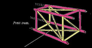

Model creation: A CAD model of the fuselage truss is imported into FEA software like Ansys Workbench.
Material definition: The appropriate material properties are assigned to the truss elements (e.g., aluminum alloy, composite materials like CFRP).
Load and boundary conditions:
Loads: Simulate flight loads, such as pressure on the fuselage, and loads from other components like wings, engine, and landing gear.
Boundary conditions: Apply constraints to represent how the structure is supported, such as fixing certain edges.
Meshing: The geometry is discretized into a mesh of smaller elements (e.g., beam or shell elements) for the analysis to solve.
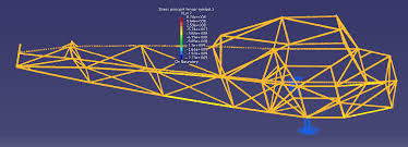
Solution: The FEA solver calculates the stresses, strains, and deformations throughout the structure based on the applied loads and boundary conditions.
Post-processing: Results are visualized as plots and animations to show how the truss deforms and where the highest stresses occur.